The Wiring Regulations inform us that every installation should be inspected and tested during erection and on completion before being put into service, to verify that the requirements of BS7671 have been met. In other words, we should always inspect and test our work before handing it back to the customer.
We will focus here on how we can achieve this requirement for 13 amp socket ring circuits as would often be installed in domestic premises. The principles can, of course, be applied to any ring circuit.
We have made a point of explaining each test in a little more detail than would normally be found in testing books, we believe that if you know why you are testing a certain way then you are more likely to carry out the test correctly and also to know when the results are indicating a fault or problem.
There are several publications that are of use to us and we will use the 18th Edition versions of these books. Do not worry if you do not have these to hand, we will provide enough information in this article for you to understand the process.
They are …
The Wiring Regulations – BS7671:2018 18th Edition
The On-site Guide to 18th Edition
Guidance Note 3 to 18th Edition
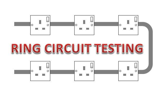
WHAT IS A RING CIRCUIT?
In a ring circuit, each of the conductors – L-N-E – form a ring around the installation. Starting at the consumer unit or distribution board a conductor will visit, or daisy chain, to each point of use on the circuit. On reaching the last point of use it will not stop but will in fact return back to the consumer unit. So there will be two Line conductors into the same circuit breaker, one conductor going out and the second conductor returning.
The Neutral bar will have two conductors also, one out and one in; and so too will the Earth bar, one out and one in.
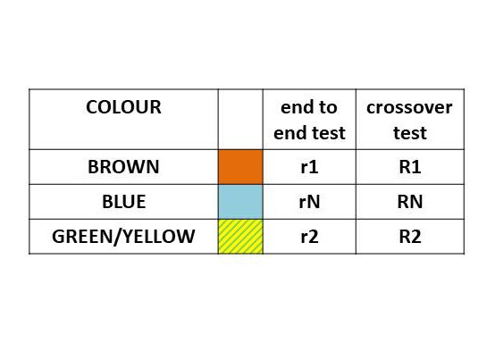
NAMES AND SYMBOLS FOR THE CONDUCTORS
There are six symbols associated with the resistances of the circuit conductors.
R1 with a capital letter is the effective resistance of the phase conductor to be used in a Zs measurement.
RN with a capital R is the effective resistance value of the Neutral conductor, but is not used in Zs measurements.
R2 again with a capital letter is the effective resistance value of the cpc or circuit protective conductor and is used in the same Zs measurement as above.
r1 with a small letter r, is the actual end to end resistance measurement of the Line conductor
rN with a small letter r again is the actual end to end measurement of the Neutral conductor
r2 small r again is the actual end to end reading of the cpc (earth) conductor
Notice that we do not call the brown conductor “live”. This is old terminology and is frowned upon, even though many electricians continue to this wrong expression.
So what is a live conductor? It can be the Phase/Line conductor or it can be the Neutral conductor since they both carry electrons in normal fault free conditions. The brown conductor carries energised electrons from the supply transformer into the circuit and the blue conductor carries de-energised electrons back to the transformer so that they may be re-energised and go around the circuit again.
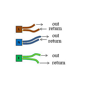
At Learn Electrics we suggest that new learners visualise this as similar to a wet radiator system. The flow pipe carries hot water from the boiler to the radiator to heat the room, this is the same as your brown wire. Having lost it’s energy or heat into the room, the return pipe carries cooler water back to the radiator to be reheated in the boiler, this is your blue wire. Having been reheated, the same water now flows back along the flow pipe to start the process all over again.
USING THE CORRECT NAMES
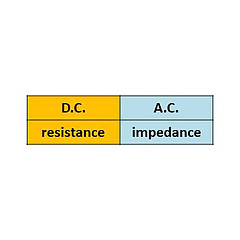
When measuring the Ohms value of a conductor we will sometimes call it a resistance and at other times an impedance, so what is the difference.
A resistance is a measurement made using a DC test voltage as we would do with our test meters on a dead circuit. Think of this as a car battery, one terminal is always positive and the other is always negative.
An impedance, on the other hand, is a measurement made on a circuit with alternating voltages present as would be the case when live testing the Zs values of a circuit. This means that when testing our ring circuit, we start off by testing the resistance and finish by testing the impedance.
Does it make a difference? Not really so long as you have your test meter set on the correct test, the meter will take care of the rest.
A DC resistance will not change in value but an AC impedance will vary according to the frequency of the supply voltage. At radio and TV frequencies in the Mega Hertz ranges the impedances will be significantly different to those measured at much lower frequencies such as 50 Hz found in our domestic dwelling. In fact, a radio is “tuned in” from the knowledge that each radio station has it’s own frequencies and we can tap into these by varying the impedance and capacitance of the electronic components.
At domestic frequencies of 50 Hz, or 50 cycles per second, the impedance and resistance are the same value within a very, very, small variance. Some purists will look on in horror if you call a Zs reading a resistance instead of an impedance, but most of us in the trade will know what you are talking about and say nothing.
Earth and CPC can cause some confusion too. According to the Wiring Regulations, the only Earth in the property is the earth conductor that goes from the service head (where the supply comes into the property) to the earth bar at the consumer unit.
All other conductors used for earthing are either bonding cables to gas and water pipes etc. or circuit protective conductors (cpc). The green and yellow conductor from the consumer unit to the sockets is a circuit protective conductor.
Again, old terminology dies hard and many electricians will still call the cpc an earth. Not only that, we buy twin and earth cable when it should properly be called twin and cpc cable. Electrics can be a mixed up world at times.
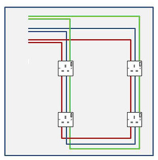
A RING CIRCUIT
So what have we got so far.
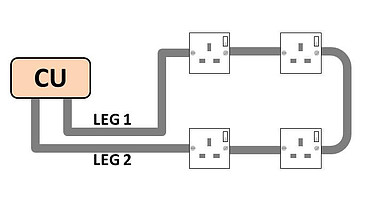
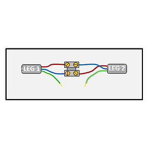
We know that a ring circuit will have two legs to it, and we imagine these as an outgoing leg and an incoming leg. Some electricians will label them as leg 1 and Leg 2, Leg A and Leg B. The Neutral and cpc will also have the same “legs”.
The first set of tests that we perform are all dead tests, i.e. the circuit is de-energised, safely isolated and locked off where necessary.
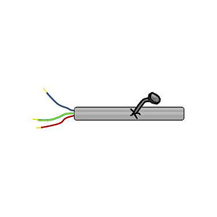
TEST 1 – CONTINUITY OF EACH CONDUCTOR
After ensuring that we have safely isolated and locked off the circuit if necessary we will begin by measuring each of the three conductors from end to end. We should have some idea of the expected values by using the data in Appendix B of Guidance Note 3.
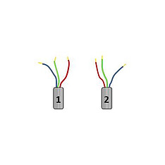
Remove the two conductors from the circuit breaker, the neutral bar and the earth bar.
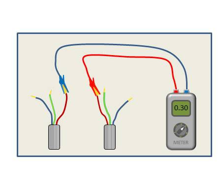
With the meter set to low ohms, measure between the two ends of the brown phase wire and make a note of the resistance reading. Let’s say it was 0.3 ohms.
Now measure end to end with the blue neutral wire and this should be almost the same value as the phase wire since both are the same size and both follow the same route around the building, so let us record 0.3 ohms for neutral.
Finally, do the same with the cpc. If twin and earth cable is used, the cpc reading will be higher since the cpc cable is thinner than the other two. It might measure 0.5 ohms and we should make a note of this.
We should have recorded…
L-L = 0.3Ω
N-N = 0.3Ω
E-E = 0.5Ω
This tells us three things.
- 1. That each conductor is showing as being continuous from end to end
- 2. The L-L and N-N readings are very similar, as they should be
- 3. If this is twin and earth, the E-E reading should be about 1.66 times bigger than L-L
These resistances all use a little r to show that they are end to end readings
L-L = r1
N-N = rN
E-E = r2
Little r is an end to end measurement as we have said. It is NOT the same as R1+R2 and little r is not recorded on the test certificates.
If your meter gives a much higher than expected reading then suspect that you have not done the test correctly, that a cable may be broken or that the conductors have been incorrectly installed in the sockets. For socket circuits you are looking for readings of a lot less than 1 ohm in an average domestic dwelling.
If the reading is much lower than expected then suspect that the conductors may be cross connected at some point or some similar problem.
TEST 2 – CROSSOVER TEST – LINE to NEUTRAL
This crossover test will check that the “balance” of the circuit is the same at each socket outlet. Large differences in readings will indicate a problem.
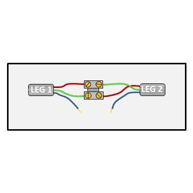
You will remember from the beginning of this article that we spoke about Leg 1 and Leg 2. We need to make use of that now.
To make the cross-connection we can use a small screwed connector block, waygos or as I used to use a pair of crocodile clips with a short connecting wire. Make sure the connection/joint is well made as we do not want the connection introducing any resistance into the test.
This now means that all the cabling in the Line and Neutral legs will be included in any measurement that we make and that the resistance reading at every socket should be roughly the same value of ohms.
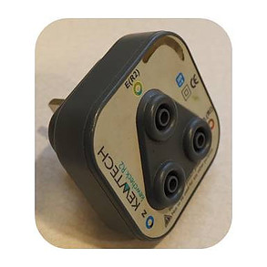
We now carry out a low ohms resistance test at each socket. Ideally use a break out plug that you can plug your leads into, some meters come with them supplied. This will mean that you do not need to open every socket to perform the test.
With the crossover configuration we have what is called a parallel circuit. Here at LearnElectrics we have produced You Tube videos and articles on resistances and Ohm’s Law if you need further information.
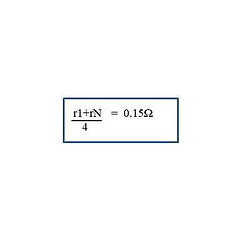
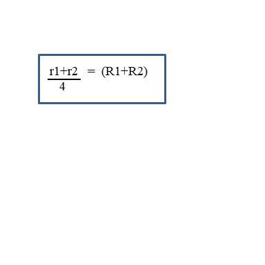
To know what resistance reading to expect, we add r1 and rN together and divide the answer by 4 (more on this later)
In our example we have 0.3 + 0.3 / 4 = 0.15 ohms
Test between Line and Neutral at EVERY socket. Remember to turn the switch on if they are switched sockets. Write down every reading as you move around the circuit and in our example we should find we get readings something like : 0.15, 0.15, 0.14, 0.15, 0.15, 0.16 etc. they are all very close to our target of 0.15 ohms, they are balanced.
A high reading could suggest a spur off the ring as extra wiring has now been included and should be investigated, for instance if the reading suddenly jumped to 0.35 ohms. We are not saying it is wrong, but we need to know where the spurs are.
If you have not cross-connected correctly so that r1 of Leg 1 is connected to rN of Leg 1 and similar with Leg 2, then you will find that the readings gradually increase as you move from socket to socket away from the consumer unit and then fall as you work your way back again. A wrong set of readings might be 0.15, 0.15, 0.17, 0.18, 0.19, 0.20, 0.1 8, 0.1 7, 0.16, 0.16, 0.15, just as an example.
TEST 3 – LINE AND CPC CROSSOVER TEST
INCLUDING R1+R2 & POLARITY
We will now cross-connect the phase and Earth and repeat the low ohms resistance test.
This test will not only confirm that the circuit is balanced and show us if any spurs are present, it will also give us the R1+R2 measurement that we need to enter on the test certificate. Additionally, we can also prove the polarity of the circuit conductors at the same time. On the sequence of testing, polarity tests appear a little later, but it is the same set-up as continuity testing so it makes sense to do it now rather than having to reassemble the test later.
We will connect the LINE of Leg 1 to the CPC of Leg 2
And we connect the LINE of Leg 2 to the CPC of Leg 1
Effectively we have cross-connected r1 and r2
To calculate in advance the resistance that we should measure with our test meter we add r1 to r2 and divide by 4. In our case this will give 0.3 + 0.5 ÷ 4 = 0.2 ohms. This calculated resistance is higher than the previous tests because the cpc conductor is of smaller cross sectional area and therefore a higher resistance.
We repeat the tests as in TEST 2. So we will use our break-out plug and test at every socket on the circuit. Because we have the phase wire connected and not the neutral, if the test gives us an acceptable reading then we must have tested along the phase wire and it is in the correct termination at the back of the socket. If this is the conductor that was in the circuit breaker then that is connected correctly too and the polarity is ok. If the socket is a switched type, operate the switch to ensure that the switch does in fact work and does turn off the phase.
Each of the resistance readings should be recorded in your notebook as before and the highest figure of all the tests will become your R1+R2 figure to enter on the test certificate. We only record one R1+R2 for each circuit and it should always be the highest value as this is the worst case reading. If the worst case is acceptable then all the other lower readings will be ok too.
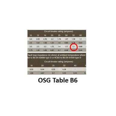
This R1+R2 will be added to Ze later to give us the Zs reading for the circuit or as we would normally do, measure Zs directly with your meter. This Zs can then be compared to standard tables in the On-Site Guide to determine if the circuit breaker will operate within the time for safety during an earth fault.
So this test has told us three things…
That the circuit is continuous and balanced
The polarity is ok
The R1+R2 reading that can be entered on the test certificate
We can now remove all the connectors or crocodile clips and the break-out plug from the sockets to leave us with the three pairs of ends L-L, N-N, E-E
INSULATION RESISTANCE
The Insulation resistance test does what it is called. It tests the pvc insulation that is around the conductors for any cracks, holes, nails, screws or anything else that might allow voltage to travel from any one of the three conductors to any of the other two.
There is an element of danger in this test as it uses an actual 500 volts DC for this test. The current is very small as the 500 volts is derived from the 9 volt battery in your test meter, but it will cause you some distress if you are touching any part of the circuit being tested or the test probes whilst carrying out this test. Always ensure that you and anyone else in the vicinity are out of harm’s way. If you are working with other electricians it is good working practice to warn them before carrying out this test.
So, to the test. The first task is to reconnect the two cpc conductors back into the earth bar. We do this so that if the phase or neutral are in any metal trunking or in proximity to any earthed metalwork and they have been damaged to the extent that they are touching the metalwork, this test will pick that up in addition to the other tests being carried out.
Ensure that the plugs have been removed from all the sockets
Disconnect any fused connection units (fused spurs) that may be connected to sensitive equipment
Any pilot lamps, neons or indicator lamps left in circuit will affect the readings and may be damaged so they should be removed where possible
Any RCDs or RCBOs that might be affected should be disconnected
SPDs should be disconnected
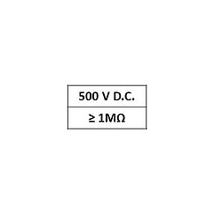
For a domestic 230 volt domestic socket ring circuit we will test at 500 volts DC and expect a reading in excess of 1MΩ. For this test, a high reading is good, we want to see millions of ohms of resistance.
Test between…
Phase and cpc (earth bar)
Neutral and cpc (earth bar)
Phase and Neutral
When carrying out an Insulation Resistance test it does not matter which end of the phase or neutral wires that you connect the probe to as we have already proved that they are both continuous from one end to the other.
A low reading should always be investigated. A new installation should read in the hundreds of Megohms but as an installation ages the value will decrease as the pvc insulation begins to degrade. The Regulations suggest the minimum value should be above 1 Megohm for a pass and anything less than 2MΩ should be investigated. Personally, I would investigate anything less than 20 MΩ.
There may of course be other reasons for a failed measurement. There could be something left in one of the sockets, there could be a fused spur to a boiler or alarm system that hasn’t been disconnected. These will need to be checked out. A neon left in circuit will typically measure 0.26 Megohms of resistance between the phase and neutral wires.
SPD’s should be disconnected or the tests only carried out at 250 volts, not 500 volts. The SPD will do its job and try to sink the 500 volts and a failed test will result.
If equipment cannot be removed from the circuit then the Regulations allow the linking of the phase and neutral wires together and to then test between these two wires connected together and the earth bar. Because the phase and neutral are linked together then effectively you have bonded them together and now, when 500 volts appears on the phase conductor, 500 volts also appears on the neutral conductor. Because both wires are at the same voltage the net result is zero voltage difference across the device or equipment. At zero volts difference the equipment cannot be damaged.
Test 4 – TESTING FOR Zs AT EACH SOCKET
Assuming that the testing of the other circuits proceeds normally and that all conductors have been re-connected in the correct locations then we will eventually arrive at live testing and the need to measure Zs. This is the loop impedance of the whole circuit from the point of use, through the consumer unit to the supply transformer somewhere down the street and back again. It is a measurement of the whole of the resistance or impedance path along which fault currents will flow. The lower the impedance, the greater the fault current. The greater the fault current the quicker the circuit breaker operates and makes the circuit safe.
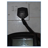
Zs should be measured at each socket on the ring. Write each result in your notebook and record the highest value on the certificate. Most multifunction test meters will be supplied with a test lead that has a moulded 13 amp plug on one end. It is simply a case of plugging in, switching on and recording the results. A whole room full of sockets can be tested in just a few minutes. If you do not have the moulded plug lead, then use the break-out plug that was used for testing R1+R2 earlier.
A RECAP
A brief recap on the sequence of test in this article for ring circuit testing.
Safe Isolation to prove the circuit is dead.
Continuity of each conductor L-L, N-N, E-E to give r1, rN and r2
Crossover test Phase and Neutral
Crossover test Phase and Earth to give R1+R2 and Polarity test at the same time.
Insulation Resistance test
When the circuit is live
Zs is measured at every socket and we record the highest value on the test certificate. We can then compare our results to the standard Zs tables in the On-Site Guide.
This has been an introduction to Ring Circuit Testing. The best way to really understand the testing is to practice and practice. Use these simple instructions on site, write down your results, even draw the circuit that you are testing.
Ring Circuit testing is not difficult, but if you intend registering with a Part P scheme provider, you can bet your boots that the assessor will ask you to show him how you test a ring circuit if you have installed one.
If you can test a ring circuit, you can test anything.
Good luck
Dave