 COLUMN NUMBERING NOTES
When completing a Schedule of Test Results it is important that the correct data is entered into the correct boxes on the schedule. The Schedule of Test results will be used for comparison checks of the circuit in the future, for example at the next Periodic Inspection. It is imperative then that every effort is made to achieve accuracy of testing and accuracy of recording.
One subject that is often an area for concern is entering the correct data into the columns of the Circuit Details section and the Test Results section, especially if completing test certification is new or unfamiliar to you.
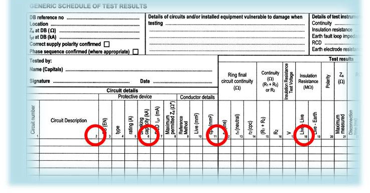
A Schedule of Inspections is shown here and the column numbers have been highlighted with red circles for ease of recognition.
Below, we show details of the required information for the two sections. These are based upon the recommended requirements of the IET, the body that issues the Generic Certificates – the certificates or Model Forms upon which all other organisations and businesses base their own certificates and forms.
At the end of this post we have provided a link to our video on completing a Schedule of Test Results
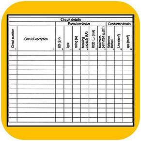
Columns 1 to 11 are for the Circuit Details section and can be completed by inspection only and knowledge of the circuit.
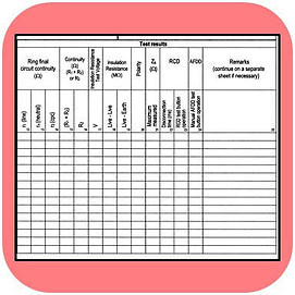
Columns 12 to 24 are for the results of the various tests that will be carried out – the Test Results
Column 25 is a remarks column that can be used for recording any useful information or observations.
CIRCUIT DETAILS SECTION
COLUMN 1 – CIRCUIT NUMBER
Enter here the circuit or device installed at each position.
For single phase circuits using 1 – 2 – 3 – 4 etc. is recommended
For three-phase supplies it is preferred to enter the phase numbers so that phase 1, phase 2, phase 3 would be designated L1 – L2 – L3 respectively. As examples, the first 3 phase block would be listed as 1L1- 1L2 – 1L3 and the fourth block 4L1 – 4L2 – 4L3.
COLUMN 2 – CIRCUIT DESCRIPTION
A brief description will suffice. Down Ring, Shower, Up lights and so on.
If you have chosen to include the way location for RCDs etc. in your chart then RCD1, RCD2 is ok.
Spare ways can be listed simply as SPARE.
COLUMN 3 – BS (EN) NUMBER
Enter the approved Standard number in this column for the device in that location.
e.g BSEN60898, BS3036 etc.
COLUMN 4 – TYPE
What is the type number of the device. For example a BSEN60898 B32 breaker would be Type B
a BSEN60898 C32 breaker will be Type C and so on. And this information is normally on the front of circuit breakers.
COLUMN 5 – RATING
Enter the nominal rating (In) for a protective device (fuse or breaker)installed in this location. Using our B32 breaker as above, the rating is 32 Amps and the C32 also has a nominal rating of 32 Amps.
COLUMN 6 – BREAKING CAPACITY
What is the stated maximum current that the protective device can safely disconnect in the event of a significant fault current flowing in the circuit. This will normally be shown on the front of MCBs as 6000. The stated Breaking Capacity should be greater than the Prospective fault Current for that circuit. Some installed devices may show a Breaking Capacity of 10000 Amps. Enter the value in kA, so for a 6000 Amp breaking capacity just enter 6 and so on.
COLUMN 7 – OPERATING CURRENT OF THE RCD IN mA
Where an RCD or RCBO is installed the trip current (IΔn) should be inserted in this column. For a 30mA device this will be shown on the front or side of the device as 30mA or as 0.03A.
COLUMN 8 – MAXIMUM PERMITTED VALUE OF Zs
Enter the maximum Zs value as per the Tabulated Values in the Wiring Regulations or the Maximum Permitted Measured Values from the IET On-Site Guide. Where the maximum permitted measured values are entered, some indication should be made on the Test Schedule, usually by making a note to that effect in the Remarks section (Column 25) for example “80% measured values quoted” or something similar.
COLUMN 9 – REFERENCE METHOD
How has the cable been installed, what reference method is it
For example reference methods B, C, 101, 102 etc.
COLUMN 10 – CONDUCTOR CROSS SECTIONAL AREA – LIVE CONDUCTORS
Enter the CSA or size of the phase and neutral conductors in mm2
– they should be the same size.
COLUMN 11 – CONDUCTOR CROSS SECTIONAL AREA – CPC CONDUCTOR
Enter the size or CSA of the circuit protective conductor in mm2
(for example the earth in twin and earth cable)
TEST RESULTS SECTION
COLUMN 12 – RING CIRCUIT “r1” RESISTANCE
The end to end resistance of the line or phase conductor in ohms is entered in this column.
Both ends of the phase conductor must be open and separate from each other and other conductors
This is called r1 in a Ring Circuit and is NOT the same as R1
COLUMN 13 – RING CIRCUIT “rN” RESISTANCE
In this column we enter the end to end resistance of the neutral conductor in ohms
Both ends of the neutral conductor are open and separate from each other and other conductors
This is called rN in a Ring Circuit and is NOT the same as RN
COLUMN 14 – RING CIRCUIT “r2” RESISTANCE
Here we enter the end to end resistance of the cpc conductor in ohms.
Both ends of the cpc conductor must be open and separate from each other and other conductors
This is called r2 in a Ring Circuit and is NOT the same as R2
COLUMN 15 – CONTINUITY OF R1+R2
R1+R2 for each circuit are entered in this column
Note that R1+R2 for radial circuits and R1+R2 for ring circuits each require a different method of measurement. Ensure the correct method is adopted. A tick may also be entered if the reading is acceptable.
COLUMN 16 – CONTINUITY OF R2
Where only the cpc resistance is measured, using the wander lead method for example, then enter the resistance value of the cpc here. This column would be used when upgrading bonding conductors for example. A tick can be entered if the reading is acceptable or the actual figures.
COLUMN 17 – INSULATION RESISTANCE TEST VOLTAGE
Enter the actual voltage that each circuit was tested at. Most often this will be 500V D.C. but where SPDs for example are left in circuit this may have been reduced to 250 V D.C.
COLUMN 18 – INSULATION RESISTANCE TEST RESULTS LIVE-LIVE
Record in this column the insulation resistance reading in Megohms (MΩ) between the phase (line) and neutral conductors.
COLUMN 19 – INSULATION RESISTANCE TEST RESULTS LIVE-EARTH
With the cpc replaced in the earth bar, measure between phase and earth and again between neutral and earth. Record the lowest (worst case) result.
COLUMN 20 – POLARITY OF THE CIRCUIT
Enter a tick into this column for each circuit after proving that the polarity of the conductors is correct and that phase is connected to the MCB or fuse.
COLUMN 21 – Zs ACTUAL
The Zs or earth fault loop impedance should be entered into this column for each circuit. It can be measured with a test meter or it can be arrived at by addition of Ze+(R1+R2).
COLUMN 22 – RCD DISCONNECTION TIME ACTUAL
Enter the measured RCD disconnection time for the x5 test. The ½ test and x1 test should also be carried out but only the five times test is recorded.
COLUMN 23 – RCD TEST BUTTON OPERATION
Enter a tick into this column if the RCD operated (tripped) when the test button was pressed.
COLUMN 24 – AFDD TEST BUTTON OPERATION
If an AFDD (Arc Fault Detection Device) is installed, press the test button and enter a tick here if the device operates. Otherwise enter n/a
COLUMN 25 – REMARKS
Any relevant notes can be entered into this column. They could include, for example, the fact that sockets with built-in USB chargers were removed before testing, or that PIR security lights were linked out before insulation resistance tests were performed. Treat it as your scribble pad of useful notes.
If you would like to view our video on how to complete a Schedule of Test Results, click on the link …
https://www.youtube.com/watch?v=Uqit2fpaYQc
Good luck and keep learning
Dave