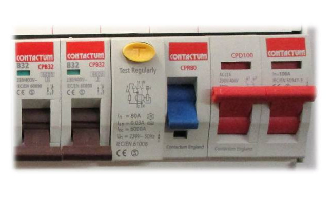
We are sometimes asked why the Wiring Regulations have disconnection times for electrical circuits.
And what is the purpose of knowing how quickly a fuse or circuit breaker should disconnect an electrical circuit during a fault.
The permitted time to disconnect from the electrical source and to make safe the circuit is very much dependent upon the voltage of the circuit and a few other factors. It is all about ensuring that an electrical shock is survivable by an average, healthy adult.
We will be using information and numbers from the Wiring Regulations, BS7671 18th Edition.
DISCONNECTION TIMES
The disconnection time, the time taken for a circuit breaker to cut off the electrical supply during a fault is a big factor in someone surviving an electrical shock. The bigger the voltage, the bigger the danger of injury or death, and as you will see, as the voltage increases, the time to disconnect becomes more critical. The quicker that a circuit can disconnect the supply during a fault, the safer the circuit is.
Once we know what the disconnection time should be for safety, according to the regulations, then we can use the tables in the Wiring Regulations to determine what the maximum Zs or loop impedance is for different circuits. And if our circuit meets the requirements for Zs, or loop impedance as it is called, then we should be confident that it will meet the required disconnection times. The lower the Zs of the circuit, the greater the fault current that flows and the quicker the disconnect times.
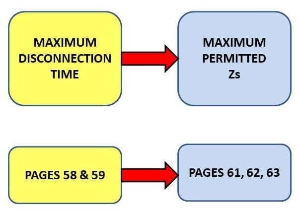
So now that we know why we have disconnection times, where do we get the information from?
Let’s start on page 58 of the 18th Edition Wiring Regulations book to determine the disconnection times and then we can look at pages 61 onwards to find the maximum Zs values.
On page 58 you will find Regulation 411.3.2.2
This tells us that we should use the disconnection times in TABLE 41.1 on page 59 for FINAL CIRCUITS
with a rated current not exceeding 63 amps for a circuit that has one or more sockets
or not exceeding 32 amps for a circuit supplying fixed equipment only.
FINAL AND DISTRIBUTION CIRCUITS
The next question is – What is a FINAL CIRCUIT
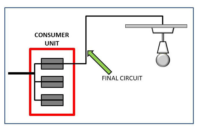
Imagine a lighting circuit in a house
The cables that leave the consumer unit and go to the luminaires are the last part of the journey for the electricity from when it left the power station to the point of use, in this case the light.
That piece of cable in the house is the final part of that journey. There are no more fuses or consumer units, this is the FINAL leg. This is a FINAL circuit.
The sockets are the same – a FINAL CIRCUIT.
So is the shower, the cooker and any other circuit that leaves the consumer unit and goes just to the points of use; they are all a FINAL CIRCUIT.
Just to clear up any confusion, a final circuit that includes fused connection units, or fused spurs as they are sometimes called, with BS1362 fuses of 13A or less is still a final circuit.
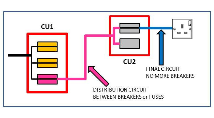
Now suppose that we take a cable from the consumer unit and run it into the garage and terminate this into a second consumer unit to supply sockets and lights in the garage.
This cable that connects the two consumer units is NOT a FINAL CIRCUIT as there is another set of circuit breakers to go through. This is what we call a DISTRIBUTION CIRCUIT.
It is DISTRIBUTING electricity from one consumer unit to another consumer unit, or from a distribution board to another distribution board or consumer unit.
The cables leaving the second consumer unit and going to the sockets or lights are FINAL CIRCUITS as before as they do not have any more circuit breakers to pass through.
So, final circuits – the last piece of cable to the various points of use
Distribution circuits – there are more circuit breakers down the line
Consumer units and distribution boards can contain both Final and Distribution circuits.
If you want to know more about final and distribution circuits we have a great video on YouTube called
ELECTRICAL FINAL CIRCUITS AND DISTRIBUTION CIRCUITS.
We will leave a link at the end of this article
FINAL CIRCUITS
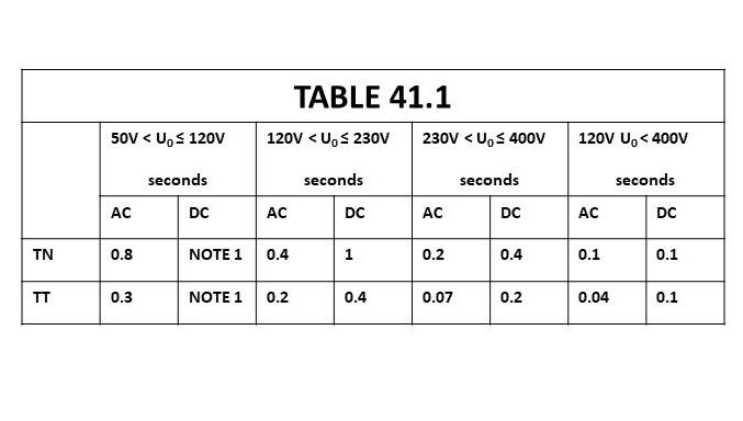
If the circuit meets the previously mentioned Regulation 411.3.2.2 then …
it will be a final circuit
and it will not exceed 63 amps for a circuit with sockets
nor will it exceed 32 amps for a circuit with fixed equipment only
And the Regulations tell us to use Table 41.1 on page 59 to determine the required maximum disconnection times.
USING TABLE 41.1
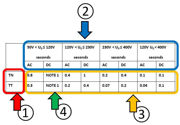
We are going to use TABLE 41.1 now for a few examples of circuits that DO meet the Regulation above.
First of all, let’s take a look at Table 41.1 and see how the table works and how we can use the information to arrive at the disconnection time that will help us to determine the Zs value that we should compare our actual test results against.
On the left of the table, number 1 and highlighted in red here, we have a choice of earthing system
either TN for TN-S or TN-C-S systems
or TT for those systems using earth rods or similar.
At the top of the table, numbered 2, we have four voltage ranges to choose from and it is important to choose the correct range. Within each range we have a further choice of AC voltages or DC voltages.
The bottom part of the TABLE, numbered 3, will give the disconnection time in seconds.
There are two entries here, numbered 4, that tell us to look at NOTE 1 for this table.
Note 1: Because this is a DC voltage and the maximum voltage for this range does not exceed 120 volts it falls into voltage Band One. This voltage band is extra low voltage and does not require protection to be provided against electric shock. The Wiring Regulations assume that at 120 volts DC you are unlikely to receive a fatal electric shock.
U0 WHAT IS IT?
Let us return to the voltage ranges at number 2 on the table above, and as an example let’s look at the range 120 volts to 230 volts.
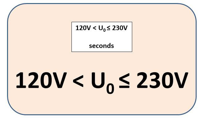
The range uses some symbols that we must pay proper attention to.
U0 (pronounced U zero) is the nominal voltage to earth. In a domestic property U0 is the nominal voltage between LINE and EARTH which we call 230 volts. It is NOT the voltage you measure, it is the assumed voltage, the nominal voltage.
We always use the nominal 230 volts for all of our calculations even if the circuit measures 240 volts.
The symbol “<” means greater than and the symbol “≤” means equal to or less than.
Looking at this arrangement of symbols, it is saying to us
U0, the nominal voltage between line and earth, is greater than 120 volts and equal to or less than 230 volts.
EXAMPLES
Let us use the Table to work out a few examples.
Starting with Example 1
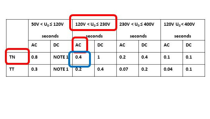
A domestic property is fed by a 230 volt TN-S system, what is the disconnection time?
Looking at the table we can find the row TN for a TN-S system on the left
At the top choose the voltage range 120 to 230 since our nominal voltage does not exceed 230 volts.
It is AC so choose the correct column.
Where the column and row meet is the answer, here in blue, it is 0.4 seconds.
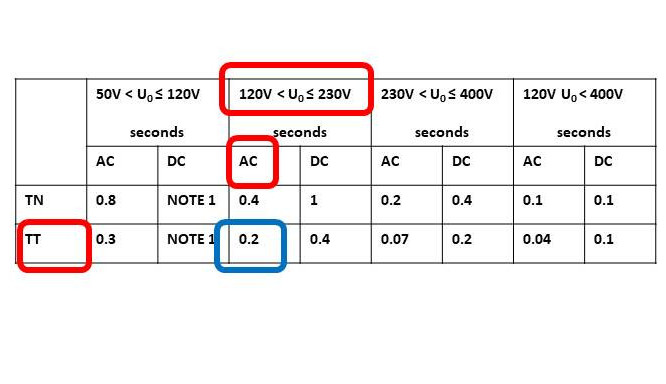
Example 2 is another domestic property but this time a TT system.
First we choose the row for a TT system
Next we can choose the voltage range 120 to 230 again
It is an AC circuit and where the two cross is our answer 0.2 seconds.
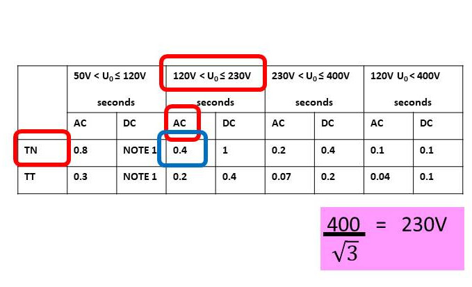
This example, number 3 is for a commercial property fed by a 3 phase 400 volt TN-C-S system.
400 volts is the voltage between LINES and this is called UL not U0
U0 is calculated by dividing the LINE TO LINE (UL) 400 volts by the square root of 3 which is 1.732
Calculating this, 400 divided by 1.732 will give us 230.9 volts which we round DOWN to 230V
So for a 400 volt 3 phase system, U0 is 230 volts
The rest of the calculation is the same as before
Choose a row, choose a voltage range and the disconnection time is 0.4 seconds.
Last one, example number 4
Another commercial property but this time with a 440 volt TN-C-S system.
First calculate U0 again. This time the LINE TO LINE voltage is 440 volts.
440 divided by 1.732 gives us 254 volts.
254 volts puts us in the voltage range greater than 230 volts but less than or equal to 400 volts.
Follow the same procedure as before, find the earthing system, choose the correct voltage range, is it AC or DC and we should find that the maximum disconnection time for this example is 0.2 seconds.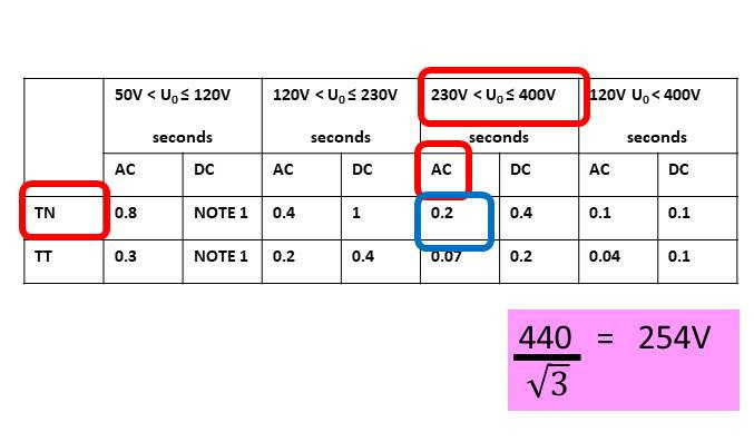
CIRCUITS THAT ARE NOT FINAL CIRCUITS
Now we can look at circuits that DO NOT meet Regulation 411.3.2.2
A circuit that is NOT a FINAL CIRCUIT
OR it is a circuit with one or more sockets, and the circuit is greater than 63 amps
OR it is a circuit rated above 32 amps supplying fixed equipment only
In this case, the disconnection time is very easy
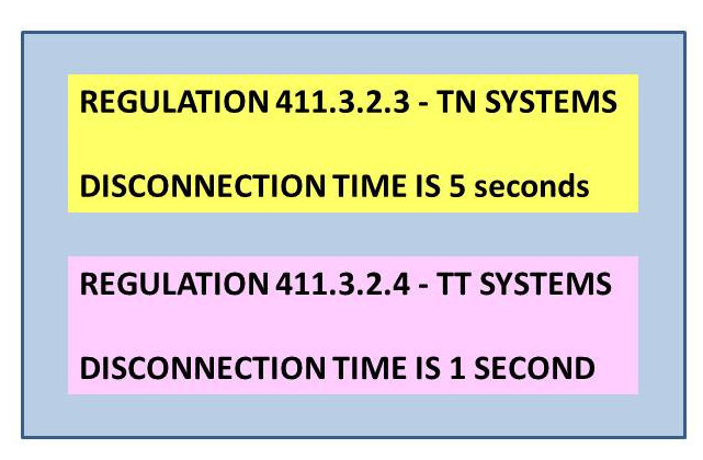
If it is a TN system Regulation 411.3.2.3 applies
If it is a TT system then Regulation 411.3.2.4 applies
Regulation 411.3.2.3 for TN systems tells us the disconnection time for any TN-S or TN-C-S circuit that does not meet 411.3.2.2 or is a distribution circuit is 5 seconds regardless of the voltage
Regulation 411.3.2.4 for TT systems tells us the disconnection time for any TT circuit that does not meet 411.3.2.2 or is a distribution circuit is 1 second regardless of the voltage
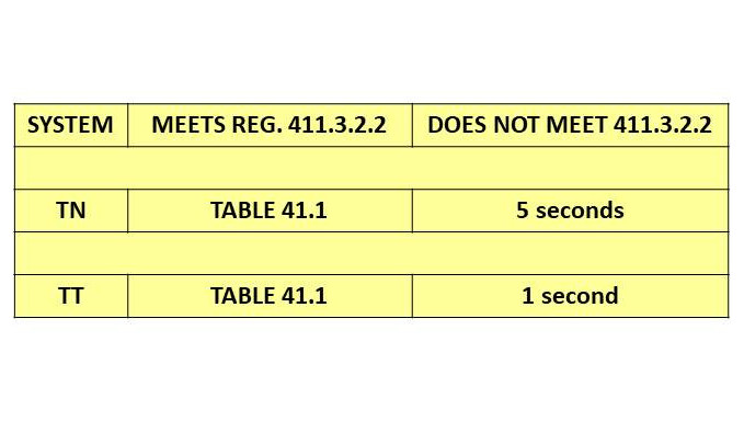
So it really is a quite simple exercise, is it a final circuit that meets Regulation 411.3.2.2, yes or no, is it a TN system or a TT system, yes or no and here we have put the last few slides into one table.
If Regulation 411.3.2.2 is met then we must use TABLE 41.1
If Regulation 411.3.2.2 is NOT met then we must use 5 seconds for TN systems and 1 second for TT systems.
FINDING Zs VALUES
Now that we know the disconnect times we can find the maximum Zs for the circuit, and it is Zs that we test when completing our electrical certificates. If our circuit does not exceed the maximum Zs value then it is assumed that it will also not exceed the maximum disconnection time.
CIRCUIT BREAKERS & RCBOs
First, let us look at TABLE 41.3 on page 62 of the WIRING REGULATIONS
The top of the table tells us that this table is for BSEN 60898 CIRCUIT BREAKERS and BSEN 61009-1 RCBOs and it also tells us that it is for 0.4 second disconnection times which are final circuits and also for 5 second disconnection times which generally implies distribution circuits.
It is the same table for any circuit using BSEN 60898 CIRCUIT BREAKERS and BSEN 61009-1 RCBOs
That makes it easy, all the information is on the same page. Make sure that you select the correct part of the table for the Type B, Type C or Type D breakers.
FUSES
Now we can look at table 41.3 on page 61.
This is for fuses and specifically for 0.4 second times and this again implies FINAL CIRCUITS
Notice that fuse sizes shown do not go past 63 amps on his table as you would expect.
Make sure you are looking at the correct type of fuse, for example is it a BS88-2 or a BS88-3, they are on the same page, on the same table, they are next to each other but they have different Zs values. Choosing the wrong Zs could impact on the required disconnection time.
On page 63 we find table 41.4
This is for fuses again but specifically for DISTRIBUTION CIRCUITS with 5 second disconnection times
On Table 41.4 the fuse sizes do in fact go beyond 63 amps, and this is correct for this table.
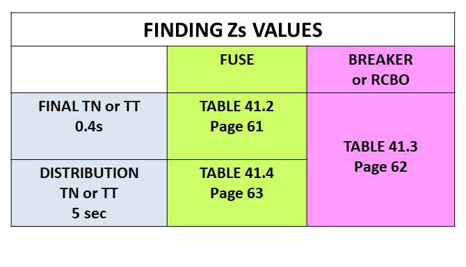
The table shown here should help you to visualise this.
Decide if it is a Final or Distribution circuit on the left and choose a row.
If it is a fuse make your selection in the green column and find the Zs in the appropriate table shown, either 41.2 on page 61 or 41.4 on page 63
If it is a circuit breaker or RCBO use table 41.3 on page 62 to find the Zs
TABULATED Zs & MEASURED Zs
These tables all show what are called tabulated figures. They are a table of figures that have been compiled from data in Appendix 3 of the Wiring Regulations and have had an allowance made for voltage fluctuations.
But an adjustment for temperature variations has not been made and we must find the measured value ourselves by applying the 80% rule or consult Table B6 in the On-Site Guide for example.
When on-site we need to know the measured values; when we measure something with our test meter, what figure should we be comparing it to directly.
To find the measured values multiply the numbers for Zs in the Wiring Regulations by 0.8
This is what we call the 80% rule and this is the Zs you should measure with your test meter.
Tabulated value x 0.8 = Maximum permitted measured value
_____________________________________________________________________________
We hope that you found this article from Learn Electrics both useful and enjoyable and that you have added more knowledge to your mental toolbox.
We also have a very active YouTube channel.
Type in LearnElectrics all one word, into the YouTube search bar and you will have access to all our videos on many electrical topics.
There is a companion video to this article on YouTube called
ELECTRICAL DICONNECTION TIMES
And this can be found by using the following link …
https://www.youtube.com/watch?v=14XPKfUaDdI
If you want to view our video
ELECTRICAL FINAL CIRCUITS AND DISTRIBUTION CIRCUITS
then please follow this link
https://www.youtube.com/watch?v=Jsqx7b9VdyM
To view all of our videos click the link below
https://www.youtube.com/channel/UCYaJQnpO4XAp0yCgqzMkmfA
Thank you, and we hope to see you again very soon.
David
