We are often asked what is an adiabatic formula or equation and indeed what does adiabatic actually mean in relation to electrical installation work. We know it is to do with selecting the correct size earth conductor but how do we use it? And why do we even bother?
If we look in the Wiring Regulations Book we will find two Formulas to do with the Adiabatic Equation, so let’s start with what adiabatic means and then move on to what the formula is and what we can do with it. We will end with some worked examples of the equation in use.
WHAT DOES ADIABATIC MEAN?
A dictionary definition would be …
Relating to or denoting a process in which heat does not enter or leave the system concerned.
Another way to look at it is to imagine a perfectly insulated box. It is so perfectly insulated that no heat can enter the box, even leaving it in the sun all day will not cause any heat to enter into the inside of the box. Nothing can leave the box either, any heat generated inside the box cannot seep through the walls of the box and escape into the atmosphere. Imagine it as a perfectly sealed heatproof unit.

This perfect scenario, which we cannot achieve in everyday life, is used as a starting point for calculating the heating effect that electrical current has on electrical conductors. We know that as current passes through the cables, there will be heat generated by this current flow. More current and the potential is there for more heat production. In the perfect situation described in the preceding paragraph no heat would be lost from the cables into the surrounding air or building materials. This perfect adiabatic scenario is actually the worst case condition for our cables. We want them to lose heat. A temperature rise is not what we want, it is inevitable though and we must design circuits and select cable sizes to make allowances for the heat rises.

With pvc plastic sheathed cables we generally assume that the limiting temperature for the cable is 70°C and any rise in temperature in the conductor should be kept below this figure. If we assume the worst case scenario i.e. no heat loss from the cables we can, with the equation, determine a cable size that will ensure that the temperature rise stays within the limits that we know will be safe for that cable. Because we have calculated figures based on the worst case we know that the conditions will not get worse, in fact in everyday situations the conditions are actually better, we will lose heat into the air and into the brickwork etc. By making the cable size match the worst case we know that the cable is unlikely to exceed its limiting temperature.
On the other hand, we do not want to install just any big cable, copper is expensive and someone has to pay for it. If the cable is unnecessarily over-sized then you or your customer are paying for extra copper that is not needed. Professional standards tell us to do the job properly.
ANSWERING THE QUESTION
When performing these calculations there are two questions that we need to be answered.
And these are that, during an earth fault…
- 1. Will the circuit breaker or fuse disconnect the circuit before the limiting temperature of the cable is reached?
- 2. And, what is the minimum size conductor that will adequately do the job?
There are three methods that we can use to answer these questions. Two are very easy calculations and the third method is by reference to a look up table and we will look at all three methods.
A calculation can be made using the formula that begins with “t” for time. This will tell us how long it takes for the cable to reach the limiting temperature.
A second calculation that begins with “S” for size of conductor will give us the minimum size cable to do the job adequately.
The third method is by using a look-up table based on the size of the Phase and Neutral conductors.

There is also the “k” factor to consider. This is a number that takes into account things like the resistivity of the conductor, in other words, how easily current can flow through it. The “k” factor also considers the temperature coefficient of the cable and it’s heat capacity since the various materials used in the construction of a cable will affect the heating up and cooling down of different types of cable. Think of the “k” factor as just a number that makes the equation work for different types of cables.
THE LIMITING TEMPERATURE
We now know that a cable will begin to heat up when a current passes through it. More current, more heat. The limiting temperature for grey twin and earth cable is 70°C, for white heat resisting cable used for immersion heaters it is 90°C. The cables have been constructed differently and use a different blend of materials in the plastic. We must design a circuit such that the limiting temperature is never exceeded.
We will look at these three methods in more detail and then look at some examples.
THE TIME FORMULA

This formula is used to calculate the time taken for the protective conductor or Earth conductor to reach it’s limiting temperature. In BS7671:2018 this is shown on page 92.
In a TN system (i.e TNCS or TNS) there are two disconnection times stated in the Wiring Regulations.
For a 230 volt final circuit up to a certain current load the circuit breaker or fuse must disconnect within 0.4 seconds. Final circuits above the stated maximums and any TN distribution circuits have been given a 5 second disconnection time. These times can be found in Regulations 411.3.2.2 and 411.3.2.3 of the Wiring Regulations and in Table 41.1 of the same book (pages 58/59 of BS7671:2018).
During an earth fault, a correctly designed circuit will have a very large fault current flowing along the protective conductors or Earth. After a short while the circuit breaker will operate and disconnect the supply but until then the massive current that flows will cause a rapid temperature increase in the conductors.
If this was a TN domestic final circuit we would expect the breaker or fuse to disconnect the circuit in 0.4 seconds or less. If, by using this formula we calculate a time of greater than 0.4 seconds then we can deem the cable to be at least the minimum size to do the job safely. The breaker will operate before the cable reaches the limiting temperature and when the breaker operates the current will stop flowing and the cable will begin to cool down, the cable is safe.
If for example we calculated that the cable would reach the limiting temperature in 0.5 seconds and the circuit breaker operated in 0.4 seconds then that is a full one tenth of second before the cable would overheat. The cable has perhaps only reached 60°C before the breaker disconnects the circuit. This is a good example.
However, if the time calculation indicates a time that is less than the breaker operating time then the cable may be damaged during a fault. If the breaker time was 0.4 seconds, again, and the time for the cable to reach its limiting temperature was only 0.3 seconds then the cable will reach 70°C a full one tenth of a second before the circuit breaker operates, it may be well above 80°C before the circuit disconnects. This is an unsatisfactory situation and the cable may be damaged.
As you can see, we have a problem now. It is not usually an option for us to reduce the amount of fault current that is flowing so the only real option is to increase the cable size since larger cables take longer to heat up. We might choose to increase the cable from 2.5mm2 to 4mm2 and recalculate the times again.
THE SIZE FORMULA

The formula shown here is a transposition of the above time formula. It has been rearranged to make the size or “S” the subject. It can be found on page 196 of BS7671:2018. This is the most useful form of the equation because, as electricians, we want to know what size cable to buy and install. We want a cable that is big enough to do the job safely but not so big that it has cost too much money.
If we know the fault current that will flow and we know the maximum disconnection time for the type of circuit and we know the cable type, we can calculate the minimum size earth conductor required. We use the term earth here to include the circuit protective conductors or cpc of cables. It is one of those anomalies of electrics that we buy twin and earth cable but the earth that is in the twin and earth cable should properly be called a cpc or circuit protective conductor according to the Wiring Regulations. Whether we call it an earth, a cpc or a protective conductor, we all know which piece of copper conductor we are talking about.
Using this arrangement of the formula may give us an answer of say 1.2mm2
for the earth. If this was grey twin and earth cable this would lead us to choose 2.5mm2 twin and earth with a 1.5mm2 earth, a standard size cable. The earth conductor, at 1.5mm2 , exceeds the minimum size required of 1.2mm2.
A LOOK UP TABLE
The third variation is a look-up table as found on page 198 of BS7671:2018. We do not calculate the size using the adiabatic equation now, but instead choose fixed sizes from values selected by our knowledge of the size of the Live conductors i.e. the Phase or Neutral conductors. This method will almost always give a bigger size than is required but it should never be too small.
Let us now look at some calculations.
A CALCULATION WITH THE TIME FORMULA

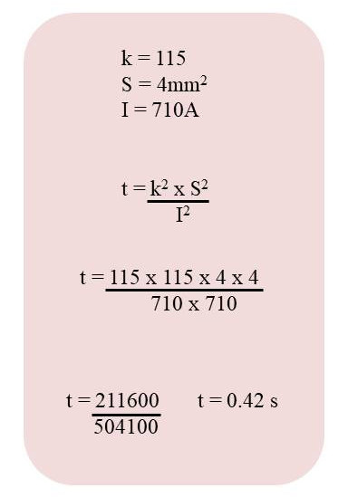
As we saw earlier the equation to calculate the time taken for a conductor to exceed the limiting temperature is given by the formula shown here on the right.
For this example we will assume that we are dealing with a domestic final circuit in a kitchen. It is a TNCS circuit and the maximum disconnection time is given as 0.4 seconds. If we look at the table for values of k in the Wiring Regulations book on page 92 we see that the k value for our 70°C pvc thermoplastic cable is 115. We have also measured PFC, the prospective fault current, with our meter and we know this to be 710 amps for this example.
Question. How long will it take this cable to reach 70°C with 710 amps of fault current flowing?
The formula shows that the values are squared – that is k2, s2 and I2. Any number squared is simply that number multiplied by itself. So, 32
, pronounced three squared, is simply three multiplied by three; so 32
= 3×3 = 9.
52
= 5×5 =25 and so on.
k2
= k x k
Our top line is therefore k2 x S2 which is k x k x S x S
This is 115 x 115 x 4 x 4 = 211600. Write this number down, you will need it in a moment.
The bottom line is I2 or I x I = 710 x 710 and gives us 504100. Write this number down too.
The equation tells us to divide the first number by the second i.e. divide the top line by the bottom line.
So 211600 divided by 50411= 0.42 seconds.
The answer tells us that the cable will reach it’s limiting temperature of 70°C after 0.42 seconds. But, the circuit breaker will operate in 0.4 seconds or less and so the circuit will disconnect before the cable reaches 70°C, before it is damaged. A safe circuit from this perspective.
CALCULATING THE SIZE OF THE CONDUCTOR

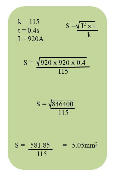
The formula for “S” or size is shown on the right and can be found in the Wiring Regulations book on page 196 and the k values are repeated in Table 54.3 on page 197.
Now we have a square root calculation to do. Most calculators will have a square root button on them. Look for the √ symbol, sometimes with the number 2 next to it – 2√.
Many mobile cell phones have two calculator modes, simple mode with the phone upright and scientific mode with the phone turned 90 degrees on to the side. You will find the square root symbol √ in the scientific mode.
What does square root do. It answers the question If I am given a number What number multiplied by itself will equal that number?
For example the square root of 16 asks the question – what number multiplied by itself will give me 16. The answer is 4 x 4 =16. So the square root of sixteen is four. √16 = 4.
√100 = 10 since 10 x 10 =100
√256 = 16 since 16 x 16 = 256
OK. Let’s do an adiabatic example. This time we need to know the smallest size earth conductor with a k factor of 115 that will carry 920 amps of fault current in a domestic final circuit with a disconnection time of 0.4 seconds.
The formula this time is very slightly more difficult but still easy to do. Just follow a logical method and write things down as you get answers. All the workings out are shown in the picture above.
The size or “S” is calculated by following the formula and we should start from the inside and work our way out.
The first step is to square the current. So I2 = I x I. This is 920 x 920 = 846,400. Write this down.
Now multiply this by t = 0.4 seconds. So, 846,400 x 0.4 = 338,560
And lastly for the top line square root that answer. √338,560 = 581.85
Now finish the calculation off. The top line divided by the bottom line.
581.85 ÷115 = 5.05mm2
The earth conductor needs to be at least 5.05mm2 and in practice this will mean 6mm2 as 4mm2 is too small and 6mm2 is the next standard size available.
METHOD THREE – A LOOK-UP TABLE EXAMPLE

This is what is known as a belt and braces method of choosing an earth conductor size. It will always give you at least the right size and most times a bigger size than necessary. But it is quick to use and helps to select a workable size.
You will need to find the table “Minimum cross-sectional area of protective conductor” in the Wiring Regulations Book, which in BS7671:2018 is Table 54.7 on page 198.
There are just three ranges to choose from to find the size of Earth conductor to use. These ranges are based on the size of the Live conductors, the Phase or Neutral and do not consider the amount of fault current flowing. They do assume that the Live conductors have been correctly selected in the first place.
How do we do this? In the leftmost column of Table 54.7 choose where the Line or Live conductor falls.
S ≤ 16 : The Line conductor size (S) is up to and equal to 16mm2 . It is NOT bigger than 16.
16 < S ≤ 35 : The Line conductor (S) is between two numbers now and a new symbol has appeared . This tells us that the line conductor (S) is greater than 16mm2 and up to and equal to 35mm2. i.e from 16.001 to 35.000
S > 35 : The last range introduces another symbol that tells us that S (the line conductor) is greater than 35mm2
The middle column will then tell us the size of earth conductor to select.
For the first row, S ≤ 16 the earth size is the same as S
If the line conductor (S) is 6mm2 then the earth is the same size as S – i.e. 6mm2
If S is 10mm2 then the earth is 10mm2 and so on
The second row shows 16 < S ≤ 35 and the middle column tells us the earth should be 16mm2 for any line conductor in this range.If S = 16 then the earth is 16, if S = 25 then the earth is still 16.
The third row is for any S above 35mm2. The earth is half the size of the line conductor.
If S is 50mm2 then the earth is 25mm2 . If S is 70mm2
then the earth is 35mm2 and so on.
We hope you have found this short introduction to the Adiabatic Equation useful and more importantly that you will be able to confidently use these formulas and methods in your work.
David
